
Bus and Minibus AC Repair Dubai
A cool driver’s vent does not prove the passenger cabin is comfortable. Buses and minibuses can use front, rear or roof-mounted equipment, several blowers, long ducts and multiple drains. Diagnosis compares zones and operating load before the failed path is selected.
Why passenger-cabin cooling cannot be judged from one vent
Long cabins experience solar load, door opening and occupancy unevenly. The front may cool first while the rear receives reduced airflow. A roof unit can have a clean supply path but blocked return, or a rear evaporator can cool while its blower, duct or drain creates the customer complaint. The inspection therefore uses a zone map rather than a single thermometer reading.
Vehicle configuration must be identified. Factory and body-builder systems can differ in compressor drive, condensers, hoses, control panels, roof modules and rear units. A registration description may not reveal the conversion. Unit labels, clear photographs and physical inspection help select service information and parts.
For a single-cab van or light truck, the commercial cab AC page is the better technical owner. When several buses need recurring reporting and downtime control, connect each vehicle-level diagnosis with the fleet program.
Cabin zones, roof equipment and distributed measurements reveal different faults
The drawings are generic educational views. Actual bus and minibus systems vary by chassis, body builder and market specification.
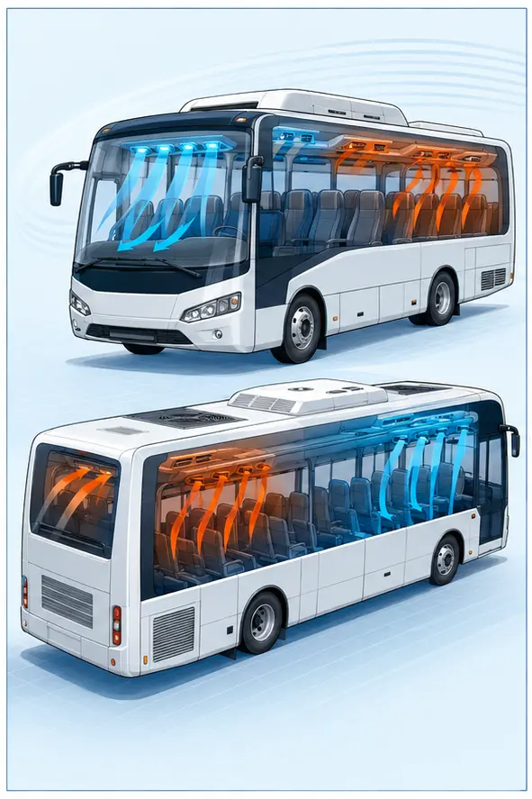
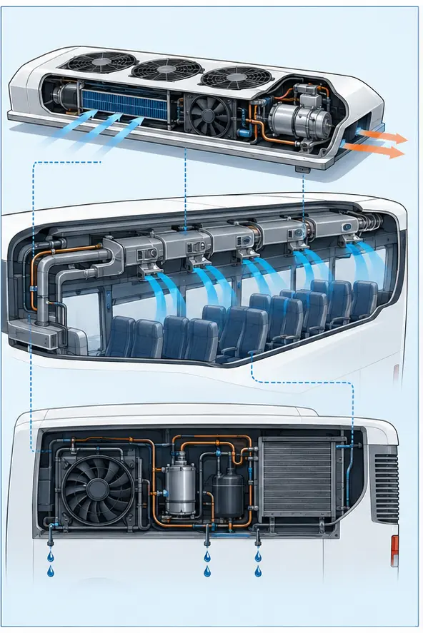
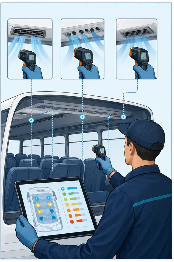
From passenger complaint to zone-specific repair
The sequence prevents a front-cabin success from hiding a rear-cabin failure.
Configuration record
Identify chassis, body builder, seating, front, rear and roof equipment, refrigerant, unit labels and control arrangement. Dimensions confirm access and bay suitability.
Zone complaint map
Mark affected rows, outlet groups, door cycles and time of failure. Driver and passenger observations are kept distinct where they differ.
Common-condition measurement
Test selected outlets, returns, blower stages and control commands under one recorded condition. The pattern points toward shared or local causes.
Unit and circuit diagnosis
Inspect the relevant blower, duct, valve, evaporator, condenser, drain, electrical circuit or refrigerant path. Safety controls roof or high access.
Repair and balance
Complete the approved work, restore joints and insulation, and ensure drains and panels are secured. A local fix should not disturb another cabin zone.
Cabin-wide verification
Retest the original zones and compare front-to-rear behaviour. The handover states passenger-load limitations and any condition not reproduced.
Zone patterns and their first investigation
The first check follows the spatial pattern rather than a familiar part name.
| Cabin pattern | Zone investigation | Configuration question |
|---|---|---|
| Driver cold, rear rows warm | Rear blower, return, duct, metering and rear evaporator path | Confirm whether the system has shared or separate controls |
| One side of cabin weak | Branch duct, diffusers, joints and local blower output | Interior changes or luggage can obstruct return and supply |
| All zones warm at idle | Condenser fans, heat rejection, compressor command and pressures | Engine or electrical warnings change the safety response |
| Water from roof vents or trim | Unit drains, hose routing, case sealing and rain entry | Do not assume every water leak is condensate |
| Strong fan noise, poor volume | Wheel condition, return restriction, duct collapse and filter | High sound can accompany recirculation starvation |
| Cooling fades as passenger load rises | Capacity, door cycles, airflow balance and refrigerant distribution | Empty-bay results need an honest operating-load limitation |
Roof access, vehicle height and body conversion are confirmed before booking. Specialized coaches and heavy systems may require another facility or scope.
Eight systems that can make one part of the cabin warmer
The sections below follow air from the unit to passengers and condensate back out of the vehicle.
Front and rear complaints remain separate
The driver area, front passenger rows and rear cabin are measured under the same blower and door conditions. Each zone can have a different outlet temperature and air volume.
The pattern indicates whether the problem begins at refrigerant production, an individual evaporator, a blower, a duct or cabin distribution. One cold vent cannot close the job.
Air must find its way back to the unit
A blocked return grille, luggage, trim or altered seating can starve a roof or rear unit even when supply vents appear open. The blower may sound strong while recirculation collapses.
Inspection includes return paths and cabin modifications. Cleaning only visible outlets will not correct a hidden intake restriction.
Multiple fans create multiple electrical loads
Roof and rear systems may use several motors, relays, controllers or speed stages. One failed circuit can reduce a section without stopping the entire system.
Voltage, command and current are checked at the affected unit. A larger fuse is never used to hide a hot connector or failing motor.
Long air paths leak and lose balance
Disconnected joints, crushed ducts, missing insulation, loose diffusers or internal debris can reduce a row’s airflow. Roof heat can also warm a poorly protected path.
The technician compares outlet volume along the cabin and inspects reachable joints. Dismantling follows evidence because headliners and roof panels can be extensive.
Several evaporators share or divide flow
A front and rear unit may share a compressor while using separate metering devices and long lines. Charge condition or a restriction can affect zones differently.
Pressures alone do not show which evaporator receives refrigerant correctly. Line temperatures, controls, valve behaviour and the exact circuit layout are considered.
Heat rejection may be remote from the engine bay
Roof, side or rear condensers can use dedicated fans and collect debris in different locations. A failed fan or restricted coil raises system stress and reduces cooling.
Safe access and roof clearance matter. Cleaning and electrical testing require the unit to be secured and isolated according to the vehicle procedure.
Every evaporator needs a clear water route
Condensate from roof or rear units should leave through designed drains. Blockage, disconnection or poor slope can wet trim, create odour or drip onto passengers.
Water location is mapped before cleaning. Rain leaks and coolant leaks remain separate possibilities, so a wet headliner is not automatically an AC drain diagnosis.
Passengers and door cycles affect pull-down
A full cabin adds heat and repeated door opening replaces cooled air. The test should distinguish expected slower pull-down from a zone that never reaches stable cooling.
Where a loaded road test is impractical, the report states the test limit. The operator should not receive an unrealistic capacity promise from an empty-bay measurement.
Quotation depth follows zones, access and vehicle configuration
A useful estimate names the affected unit and whether diagnosis covers one zone or the full system. Roof access, headliner removal, long hoses, multiple blowers and separate control panels can expand labour compared with a passenger vehicle.
Any public range is an early guide that cannot bind a multi-zone repair. The multi-zone estimate is issued after identifying, chassis and body specification, fault severity, number of units, refrigerant, parts choice, required access, supplier timing and current bay capacity.
Passenger-route pressure cannot replace verification. If the repair is completed without a fully loaded operating test, the report states that limit and identifies the return conditions that should trigger reinspection.
What a multi-zone verification should record
After repair, the technician repeats measurements at the original warm locations and at reference outlets that were performing normally. The same blower settings, door state and operating condition are used where practical. This comparison shows whether the repair improved only one outlet or restored the relationship across the cabin. Return-air temperature and fan stage can be useful when a roof unit recirculates a large volume. The report should not reduce the result to the coldest point in the vehicle.
Passenger loading may not be reproduced in the workshop, especially for scheduled buses. In that case, the operator receives an honest limit and a short route-observation plan. Drivers can note the time, affected rows, occupancy, door cycles and outside condition if the complaint returns. They should not adjust hidden controls, block returns or add refrigerant. That evidence allows a follow-up to distinguish insufficient capacity, airflow imbalance and a condition that appears only under the real route.
Cabin trim is part of the quality check because long ducts and roof equipment often sit behind panels used by passengers. Fasteners, grilles, emergency equipment access, lighting and headliner sections disturbed during the work must be restored securely. Condensate hoses are checked for slope and support so a successful cooling repair does not create a later water complaint. The final walk-through therefore includes the passenger area as well as the machine readings.
Operators should keep the final zone record with the vehicle, not only in a general fleet folder. It identifies which unit, drain, blower or duct was touched and gives the next technician a map when the same row is reported again. A later complaint in another zone can then be treated as new evidence rather than automatically blamed on the earlier repair.
Bus and minibus AC questions
Multi-zone systems require more precise answers than “cold” or “not cold.”
Why is the front cold but the rear warm?
The rear may have its own blower, duct, return, metering device or evaporator path. A shared refrigerant problem can also distribute unevenly. Zone measurements and the exact circuit layout identify the next test.
Can you service roof-mounted units?
Subject to vehicle height, safe access, unit type and bay capacity. Send dimensions and photographs before arrival. No roof work should begin from improvised ladders or unsupported access.
Does water from the ceiling mean a blocked AC drain?
It is possible, but rain entry, body seals and other water routes must be separated. The timing, liquid location and drain inspection matter. Coolant or contaminated liquid requires a different response.
Can the vehicle return to route the same day?
Only when diagnosis, approval, parts, access, repair and cabin-wide verification fit. Several zones or roof access can extend the job. The estimate gives a current target without guaranteeing operational availability before testing.
Do you offer scheduled service for several buses?
Yes, subject to a written fleet scope. Use the fleet page to define roster, reporting, approvals and downtime. Each bus still keeps its own configuration and findings.
Send the vehicle dimensions and warm-zone map
Tell us the chassis, body type, roof or rear unit, affected rows and operating pattern. We will confirm access and plan a zone-based diagnostic.