
Car AC Expansion Valve Repair Dubai
Cooling that starts normally and then fades. Metering faults are easiest to understand when the operating condition is recorded before the result is interpreted. Pressure alone cannot show how refrigerant is feeding the evaporator. A restriction theory earns confidence only when temperature, charge and airflow agree.
Identify whether the vehicle uses a thermostatic valve or electronic metering device. At the valve-to-coil boundary, recorded at a stable engine speed and cabin load. A temperature change at this point must be read beside suction behaviour. If the complaint includes a car AC hissing noise near the dash, the sound still needs to be tied to operating data before the expansion device is blamed. That comparison protects the dashboard from unjustified dismantling. For a symptom-first explanation, see our car AC expansion valve symptoms guide.
Cooling behaviour points to the next test
Frost near the evaporator inlet. Before an expansion-device quotation, repeated after the system has settled. Contamination evidence can change the job from one valve to wider circuit work. The estimate therefore needs a clean boundary between confirmed and conditional tasks.
Grinding from the compressor drive calls for ac shutdown; visible vapour, smoke, overheating or fumes calls for a safe stop and appropriate recovery advice. Metering faults are easiest to understand when the operating condition is recorded before the result is interpreted. Pressure alone cannot show how refrigerant is feeding the evaporator. A restriction theory earns confidence only when temperature, charge and airflow agree.
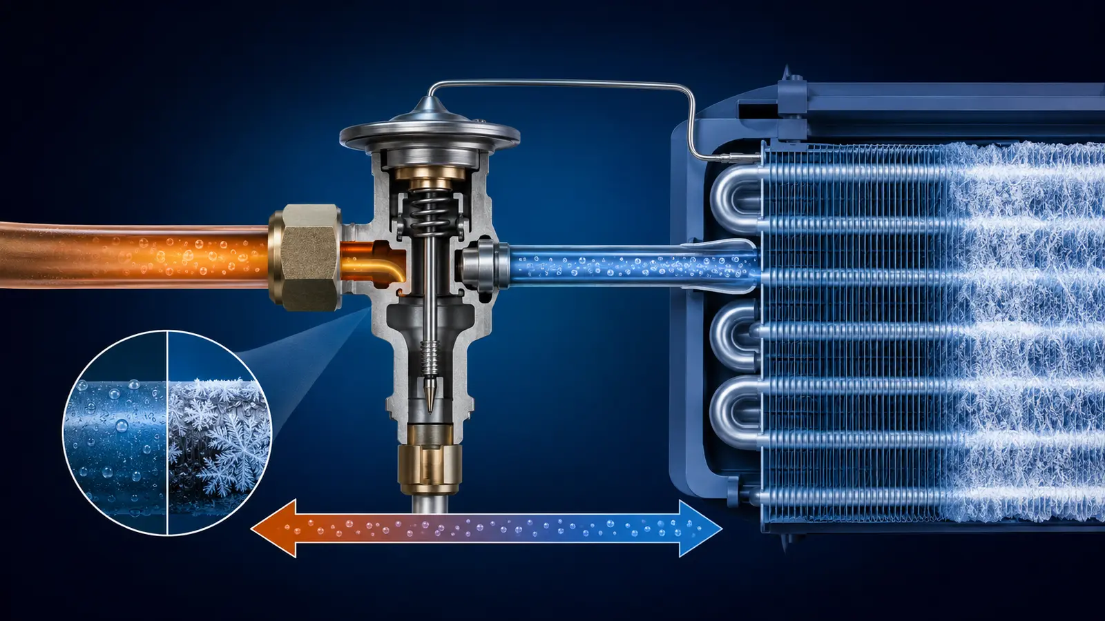
Match the symptom to the refrigerant state
Cooling that starts normally and then fades
Metering faults are easiest to understand when the operating condition is recorded before the result is interpreted. Pressure alone cannot show how refrigerant is feeding the evaporator. A restriction theory earns confidence only when temperature, charge and airflow agree.
Frost near the evaporator inlet
At the valve-to-coil boundary, linked to the exact valve type fitted to the vehicle. A temperature change at this point must be read beside suction behaviour. That comparison protects the dashboard from unjustified dismantling.
Uneven suction-line temperature
For a suspected refrigerant restriction, recorded at a stable engine speed and cabin load. Moisture, debris and a damaged line remain competing explanations. The next test should distinguish those routes before the circuit is opened.
Pressure readings that suggest restricted metering
During a stable cooling run, compared with refrigerant charge, airflow and heat rejection. A sensing-bulb or electronic command problem can alter feed without a blocked orifice. Recording the operating load makes the conclusion reproducible.
An evaporator that floods or starves
Before an expansion-device quotation, interpreted beside suction pressure and pipe temperature. Contamination evidence can change the job from one valve to wider circuit work. The estimate therefore needs a clean boundary between confirmed and conditional tasks.
Intermittent cooling after heat soak
After valve-related work, repeated after the system has settled. Evaporator feed should remain controlled while vent temperature and compressor response settle. A cold first minute is not the final acceptance test.
Six measurements that test a restriction theory
An expansion valve should not be approved from one pressure reading. The operating load, refrigerant temperatures, airflow and command data must point to the same restriction before the circuit is opened.
Identify the metering device
Confirm whether the vehicle uses a thermostatic expansion valve or an electronic metering device. The valve type determines which mechanical or command checks are relevant.
Stabilise the operating load
Record high-side and low-side behaviour at a stable engine speed and cabin load. Readings taken while the system is still changing can create a false restriction pattern.
Compare inlet and outlet temperatures
Measure the evaporator inlet, outlet and suction-line temperatures beside pressure behaviour. A temperature change at the valve-to-coil boundary needs the full refrigerant-state context.
Inspect the sensing or command path
Where fitted, check sensing-bulb position, contact and insulation. On electronic systems, compare the command and response before treating the orifice as blocked.
Exclude competing faults
Low charge, weak airflow, heat-rejection problems, compressor control and a kinked line can imitate restricted metering. Each route needs to be excluded with measured evidence.
Check contamination before replacement
Moisture or debris can change the repair from one valve to wider circuit work. The estimate should separate confirmed work from cleaning or component replacement that depends on inspection.
What can imitate a faulty expansion valve
Moisture freezing at the restriction
For a suspected refrigerant restriction, linked to the exact valve type fitted to the vehicle. Moisture, debris and a damaged line remain competing explanations. The next test should distinguish those routes before the circuit is opened.
Debris circulating from compressor wear
During a stable cooling run, recorded at a stable engine speed and cabin load. A sensing-bulb or electronic command problem can alter feed without a blocked orifice. Recording the operating load makes the conclusion reproducible.
A kinked line imitating valve restriction
Before an expansion-device quotation, compared with refrigerant charge, airflow and heat rejection. Contamination evidence can change the job from one valve to wider circuit work. The estimate therefore needs a clean boundary between confirmed and conditional tasks.
An incorrectly placed sensing bulb
After valve-related work, interpreted beside suction pressure and pipe temperature. Evaporator feed should remain controlled while vent temperature and compressor response settle. A cold first minute is not the final acceptance test.
Wrong superheat caused by charge error
Metering faults are easiest to understand when the operating condition is recorded before the result is interpreted. Pressure alone cannot show how refrigerant is feeding the evaporator. A restriction theory earns confidence only when temperature, charge and airflow agree.
Dashboard access that changes labour scope
At the valve-to-coil boundary, repeated after the system has settled. A temperature change at this point must be read beside suction behaviour. That comparison protects the dashboard from unjustified dismantling.
Clean circuit, contaminated circuit or control fault
Check contamination before approving a replacement
Before an expansion-device quotation, linked to the exact valve type fitted to the vehicle. Contamination evidence can change the job from one valve to wider circuit work. The estimate therefore needs a clean boundary between confirmed and conditional tasks.
Dashboard access that changes labour scope
After valve-related work, recorded at a stable engine speed and cabin load. Evaporator feed should remain controlled while vent temperature and compressor response settle. A cold first minute is not the final acceptance test.
Uneven suction-line temperature
Metering faults are easiest to understand when the operating condition is recorded before the result is interpreted. Pressure alone cannot show how refrigerant is feeding the evaporator. A restriction theory earns confidence only when temperature, charge and airflow agree.
Inspect the sensing bulb or electronic command where fitted
At the valve-to-coil boundary, compared with refrigerant charge, airflow and heat rejection. A temperature change at this point must be read beside suction behaviour. That comparison protects the dashboard from unjustified dismantling.
A kinked line imitating valve restriction
For a suspected refrigerant restriction, interpreted beside suction pressure and pipe temperature. Moisture, debris and a damaged line remain competing explanations. The next test should distinguish those routes before the circuit is opened.
Intermittent cooling after heat soak
During a stable cooling run, repeated after the system has settled. A sensing-bulb or electronic command problem can alter feed without a blocked orifice. Recording the operating load makes the conclusion reproducible.
Proving stable evaporator feed after the work
Compare evaporator inlet and outlet temperatures
Metering faults are easiest to understand when the operating condition is recorded before the result is interpreted. Pressure alone cannot show how refrigerant is feeding the evaporator. A restriction theory earns confidence only when temperature, charge and airflow agree.
Frost near the evaporator inlet
At the valve-to-coil boundary, linked to the exact valve type fitted to the vehicle. A temperature change at this point must be read beside suction behaviour. That comparison protects the dashboard from unjustified dismantling.
Wrong superheat caused by charge error
For a suspected refrigerant restriction, recorded at a stable engine speed and cabin load. Moisture, debris and a damaged line remain competing explanations. The next test should distinguish those routes before the circuit is opened.
Exclude low charge, airflow loss and compressor-control faults
During a stable cooling run, compared with refrigerant charge, airflow and heat rejection. A sensing-bulb or electronic command problem can alter feed without a blocked orifice. Recording the operating load makes the conclusion reproducible.
An evaporator that floods or starves
Before an expansion-device quotation, interpreted beside suction pressure and pipe temperature. Contamination evidence can change the job from one valve to wider circuit work. The estimate therefore needs a clean boundary between confirmed and conditional tasks.
Debris circulating from compressor wear
After valve-related work, repeated after the system has settled. Evaporator feed should remain controlled while vent temperature and compressor response settle. A cold first minute is not the final acceptance test.
When dashboard access is justified
Check contamination before approving a replacement
For a suspected refrigerant restriction, linked to the exact valve type fitted to the vehicle. Moisture, debris and a damaged line remain competing explanations. The next test should distinguish those routes before the circuit is opened.
Moisture freezing at the restriction
During a stable cooling run, recorded at a stable engine speed and cabin load. A sensing-bulb or electronic command problem can alter feed without a blocked orifice. Recording the operating load makes the conclusion reproducible.
Pressure readings that suggest restricted metering
Before an expansion-device quotation, compared with refrigerant charge, airflow and heat rejection. Contamination evidence can change the job from one valve to wider circuit work. The estimate therefore needs a clean boundary between confirmed and conditional tasks.
Record high-side and low-side behaviour under stable load
After valve-related work, interpreted beside suction pressure and pipe temperature. Evaporator feed should remain controlled while vent temperature and compressor response settle. A cold first minute is not the final acceptance test.
An incorrectly placed sensing bulb
Metering faults are easiest to understand when the operating condition is recorded before the result is interpreted. Pressure alone cannot show how refrigerant is feeding the evaporator. A restriction theory earns confidence only when temperature, charge and airflow agree.
Uneven suction-line temperature
At the valve-to-coil boundary, repeated after the system has settled. A temperature change at this point must be read beside suction behaviour. That comparison protects the dashboard from unjustified dismantling.
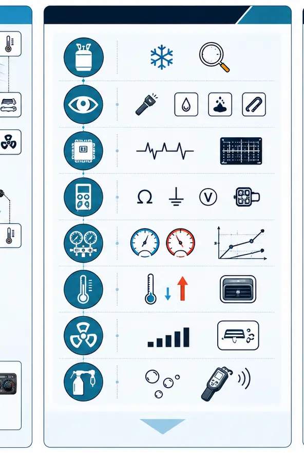
The valve cannot be judged outside the system
A wider diagnostic sequence helps confirm whether the expansion valve is the fault or whether charge, airflow, compressor control or line restriction is creating a similar pattern.
This illustration is educational. It does not claim to show a customer vehicle, a completed repair or equipment inside the Car AC Heroes workshop.
What defines the repair scope
Identify whether the vehicle uses a thermostatic valve or electronic metering device. For a suspected refrigerant restriction, linked to the exact valve type fitted to the vehicle. Moisture, debris and a damaged line remain competing explanations. The next test should distinguish those routes before the circuit is opened.
Dashboard access that changes labour scope. Before an expansion-device quotation, recorded at a stable engine speed and cabin load. Contamination evidence can change the job from one valve to wider circuit work. The estimate therefore needs a clean boundary between confirmed and conditional tasks.
Bring the cooling pattern, not a parts diagnosis
Intermittent cooling after heat soak. At the valve-to-coil boundary, compared with refrigerant charge, airflow and heat rejection. A temperature change at this point must be read beside suction behaviour. That comparison protects the dashboard from unjustified dismantling.