
Car AC Pressure Switch Repair Dubai
The compressor does not receive an enable command. Pressure-signal diagnosis begins when actual pressure is compared with a suitable physical pressure reading. A sensor can report a genuine unsafe condition or an electrical fiction. Physical and electronic values must be compared before blame is assigned.
Compare electronic pressure data with a suitable physical measurement. At the three-wire connector, tested at the connector for reference voltage, ground and signal. Reference voltage, ground quality and signal movement reveal more than a stored code. Terminal fit and moisture deserve the same attention as the sensor body.
Decide whether protection is genuine or electrical
Fans run unexpectedly. Before fitting a pressure transducer, retested without bypassing the system’s protective logic. Part calibration, thread form and sealing arrangement must match the exact circuit. Guessing from connector shape risks a wrong signal and a refrigerant leak.
Protective pressure control must never be bridged; a burning connector, smoke, abnormal engine temperature or high-voltage warning requires shutdown and correct inspection.. Pressure-signal diagnosis begins when actual pressure is compared with a suitable physical pressure reading. A sensor can report a genuine unsafe condition or an electrical fiction. Physical and electronic values must be compared before blame is assigned.
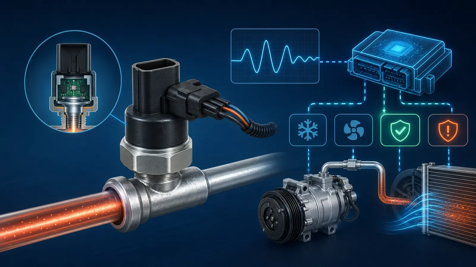
The pressure-signal decision tree
Start by comparing the electronic pressure value with a suitable physical measurement. The next test depends on whether the two values agree, not on the fault code alone.
Compare scan data with actual refrigerant pressure
A pressure sensor can report a genuine unsafe condition or an electrical fiction. Record both values under the same stable operating condition before assigning blame.
Investigate the real pressure condition
If the electronic and physical values agree, the protection event may be genuine.
- Check actual charge against the safe operating window.
- Check condenser airflow, fan response and heat rejection.
- Review compressor permission and other control inputs.
Test the electrical signal path
If the values disagree, verify the circuit before fitting a sensor.
- Measure reference voltage, ground quality and signal movement.
- Inspect terminal tension, corrosion and moisture entry.
- Check the harness near the refrigerant service line.
Use the exact wiring diagram and retest protection logic
Match the sensor calibration, connector, thread and sealing arrangement to the exact model year. After repair, scan data should move plausibly with physical pressure while the factory protection logic remains active.
Real high or low pressure can look like a bad signal
Bridging a protective switch and exposing the compressor to damage
When compressor permission disappears, checked while fan command and compressor permission change. The control module may be responding to temperature, engine load or fan status as well as pressure. The full enable logic keeps testing honest.
Condemning the sensor because pressure is genuinely too low
If pressure rises in traffic, matched to the exact wiring diagram and sensor calibration. Condenser airflow can make the sensor appear responsible for a protection event. Fan command and heat rejection belong in the same test.
Ignoring condenser airflow when pressure is genuinely high
Before fitting a pressure transducer, retested without bypassing the system’s protective logic. Part calibration, thread form and sealing arrangement must match the exact circuit. Guessing from connector shape risks a wrong signal and a refrigerant leak.
A damaged harness near the service line
After the electrical repair, compared with a suitable physical pressure reading. Scan data should track a sensible physical change while cooling remains stable. Protection should operate normally rather than being bypassed for a cold vent.
Wrong sensor calibration
Pressure-signal diagnosis begins when actual pressure is tested at the connector for reference voltage, ground and signal. A sensor can report a genuine unsafe condition or an electrical fiction. Physical and electronic values must be compared before blame is assigned.
A module decision based on several inputs rather than one switch
At the three-wire connector, checked while fan command and compressor permission change. Reference voltage, ground quality and signal movement reveal more than a stored code. Terminal fit and moisture deserve the same attention as the sensor body.
Sensor, wiring, fan control or refrigerant condition
Use the wiring diagram for the exact model year
Before fitting a pressure transducer, matched to the exact wiring diagram and sensor calibration. Part calibration, thread form and sealing arrangement must match the exact circuit. Guessing from connector shape risks a wrong signal and a refrigerant leak.
A module decision based on several inputs rather than one switch
After the electrical repair, retested without bypassing the system’s protective logic. Scan data should track a sensible physical change while cooling remains stable. Protection should operate normally rather than being bypassed for a cold vent.
Cooling cuts out at a repeatable pressure
Pressure-signal diagnosis begins when actual pressure is compared with a suitable physical pressure reading. A sensor can report a genuine unsafe condition or an electrical fiction. Physical and electronic values must be compared before blame is assigned.
Check fan response and compressor command logic
At the three-wire connector, tested at the connector for reference voltage, ground and signal. Reference voltage, ground quality and signal movement reveal more than a stored code. Terminal fit and moisture deserve the same attention as the sensor body.
Ignoring condenser airflow when pressure is genuinely high
When compressor permission disappears, checked while fan command and compressor permission change. The control module may be responding to temperature, engine load or fan status as well as pressure. The full enable logic keeps testing honest.
Intermittent cooling follows connector movement
If pressure rises in traffic, matched to the exact wiring diagram and sensor calibration. Condenser airflow can make the sensor appear responsible for a protection event. Fan command and heat rejection belong in the same test.
What the circuit test adds to the repair scope
Bridging a protective switch and exposing the compressor to damage
After the electrical repair, retested without bypassing the system’s protective logic. Scan data should track a sensible physical change while cooling remains stable. Protection should operate normally rather than being bypassed for a cold vent.
Compare electronic pressure data with a suitable physical measurement
Pressure-signal diagnosis begins when actual pressure is compared with a suitable physical pressure reading. A sensor can report a genuine unsafe condition or an electrical fiction. Physical and electronic values must be compared before blame is assigned.
The compressor does not receive an enable command
At the three-wire connector, tested at the connector for reference voltage, ground and signal. Reference voltage, ground quality and signal movement reveal more than a stored code. Terminal fit and moisture deserve the same attention as the sensor body.
A damaged harness near the service line
When compressor permission disappears, checked while fan command and compressor permission change. The control module may be responding to temperature, engine load or fan status as well as pressure. The full enable logic keeps testing honest.
Verify supply, ground and signal at the connector
If pressure rises in traffic, matched to the exact wiring diagram and sensor calibration. Condenser airflow can make the sensor appear responsible for a protection event. Fan command and heat rejection belong in the same test.
A pressure-sensor circuit fault is stored
Before fitting a pressure transducer, retested without bypassing the system’s protective logic. Part calibration, thread form and sealing arrangement must match the exact circuit. Guessing from connector shape risks a wrong signal and a refrigerant leak.
The signal must move plausibly after repair
Inspect terminal tension and moisture entry
Pressure-signal diagnosis begins when actual pressure is compared with a suitable physical pressure reading. A sensor can report a genuine unsafe condition or an electrical fiction. Physical and electronic values must be compared before blame is assigned.
Fans run unexpectedly
At the three-wire connector, tested at the connector for reference voltage, ground and signal. Reference voltage, ground quality and signal movement reveal more than a stored code. Terminal fit and moisture deserve the same attention as the sensor body.
Wrong sensor calibration
When compressor permission disappears, checked while fan command and compressor permission change. The control module may be responding to temperature, engine load or fan status as well as pressure. The full enable logic keeps testing honest.
Confirm actual refrigerant charge is not outside the safe window
If pressure rises in traffic, matched to the exact wiring diagram and sensor calibration. Condenser airflow can make the sensor appear responsible for a protection event. Fan command and heat rejection belong in the same test.
Scan data is implausible with the engine off
Before fitting a pressure transducer, retested without bypassing the system’s protective logic. Part calibration, thread form and sealing arrangement must match the exact circuit. Guessing from connector shape risks a wrong signal and a refrigerant leak.
Condemning the sensor because pressure is genuinely too low
After the electrical repair, compared with a suitable physical pressure reading. Scan data should track a sensible physical change while cooling remains stable. Protection should operate normally rather than being bypassed for a cold vent.
Open the refrigerant circuit only when the sensor design requires it
Use the wiring diagram for the exact model year
When compressor permission disappears, tested at the connector for reference voltage, ground and signal. The control module may be responding to temperature, engine load or fan status as well as pressure. The full enable logic keeps testing honest.
Bridging a protective switch and exposing the compressor to damage
If pressure rises in traffic, checked while fan command and compressor permission change. Condenser airflow can make the sensor appear responsible for a protection event. Fan command and heat rejection belong in the same test.
A pressure-sensor circuit fault is stored
Before fitting a pressure transducer, matched to the exact wiring diagram and sensor calibration. Part calibration, thread form and sealing arrangement must match the exact circuit. Guessing from connector shape risks a wrong signal and a refrigerant leak.
Verify supply, ground and signal at the connector
After the electrical repair, retested without bypassing the system’s protective logic. Scan data should track a sensible physical change while cooling remains stable. Protection should operate normally rather than being bypassed for a cold vent.
A damaged harness near the service line
Pressure-signal diagnosis begins when actual pressure is compared with a suitable physical pressure reading. A sensor can report a genuine unsafe condition or an electrical fiction. Physical and electronic values must be compared before blame is assigned.
Cooling cuts out at a repeatable pressure
At the three-wire connector, tested at the connector for reference voltage, ground and signal. Reference voltage, ground quality and signal movement reveal more than a stored code. Terminal fit and moisture deserve the same attention as the sensor body.
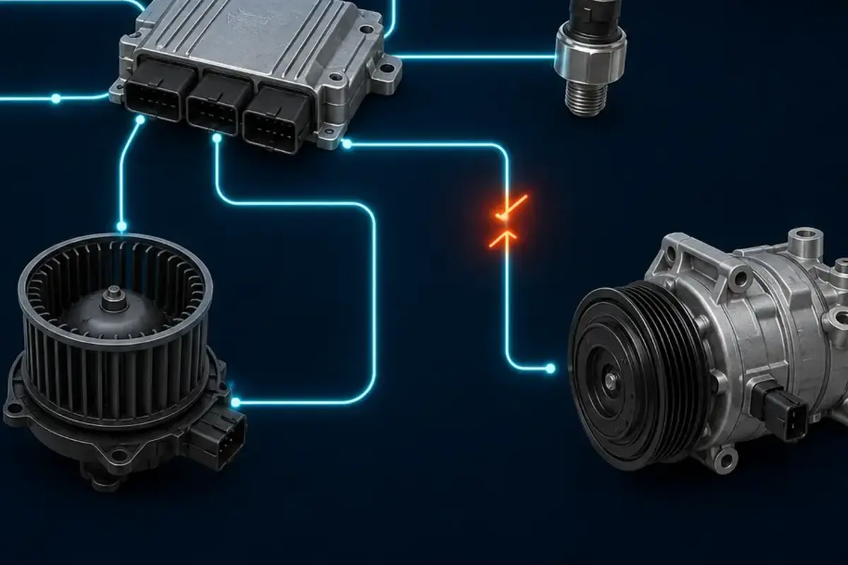
Compressor permission depends on more than pressure
The pressure signal is one input in the compressor command path. Power supply, wiring, controller logic and actual refrigerant pressure must agree.
This illustration is educational. It does not claim to show a customer vehicle, a completed repair or equipment inside the Car AC Heroes workshop.
The estimate separates electrical and refrigerant work
Compare electronic pressure data with a suitable physical measurement. When compressor permission disappears, checked while fan command and compressor permission change. The control module may be responding to temperature, engine load or fan status as well as pressure. The full enable logic keeps testing honest.
A module decision based on several inputs rather than one switch. Before fitting a pressure transducer, matched to the exact wiring diagram and sensor calibration. Part calibration, thread form and sealing arrangement must match the exact circuit. Guessing from connector shape risks a wrong signal and a refrigerant leak.
Send the code and the exact operating symptom
Intermittent cooling follows connector movement. At the three-wire connector, retested without bypassing the system’s protective logic. Reference voltage, ground quality and signal movement reveal more than a stored code. Terminal fit and moisture deserve the same attention as the sensor body.